Space Simulation
No successful satellite construction is possible without extensive testing under conditions that are as real as possible. Thermal vacuum chambers and...
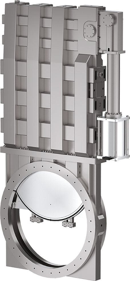
Read moreThe 19.1 Large Gate Valve series is designed for reliable isolation in applications where extra-large dimensions are required such as space simulation applications. The series are designed for up to DN 1250 mm (50"), but are available in larger sizes upon request. The Series 19.1 is configured for high vacuum up to 1 × 10⁻⁸.
All operate with a damped opening and closing mechanism based on VATLOCK technology which provides reliable sealing without any friction at the gate seal. The reduced friction increases seal life and also reduces the force required to move the gate, an important factor with larger diameters. The VATLOCK mechanism also prevents valve failure thanks to the mechanical lock-in at the closed position.
From DN 900 mm (36") and larger all series are designed with a split body for convenient maintenance. To reduce the footprint in larger DN sizes the 19.1 / 19.2 series are provide in a compact design with the double acting pneumatic actuator located to the side of the gate housing.
All of the valves in the Large Gate Valve series address the standard requirements of reliability, durability and serviceability with a special focus on high uptime and low cost of ownership.
Already operating in hundreds of applications, the 19.1 Large Gate Valve series have proven their outstanding reliability. They have become the standard for large vacuum isolation requirement in sizes from DN 400 – 1250 mm (16" – 50").


The 19.1 Large Gate Valve series can be tailored in a number of ways, such as pneumatic actuation, flange connections, ports for roughing (by-pass), venting or gauges, heat shields and many more.
Features:
Benefits:
| Sizes | DN 400 (16"), DN 500 (20"), DN 630 (25"), DN 800 (32"), DN 900 (36"), DN 1000 (40"), DN 1250 (50"), DN 1600 (63"), DN 2000 (78") |
||
|---|---|---|---|
| Actuator | Pneumatic | Double acting | |
| Body Material | Aluminum | ||
| Feedthrough | Bellows | ||
| Standard Flanges | ISO-F | ||
| Leak Rate | Valve Body | < 1 × 10⁻⁹ mbar ls-1 | |
| Valve Seat | < 1 × 10⁻⁹ mbar ls-1 | ||
| Pressure Range | 1 × 10⁻⁸ mbar to 1 bar (abs) | ||
| Differential Pressure | On the Gate | ≤ 1 bar | |
| At Opening | ≤ 20 mbar (DN 400 – 500) ≤ 10 mbar (DN 630 – 2000) |
||
| Cycles until first Service | 20 000 (DN 400 – 630) 10 000 (DN 800 – 2000) |
||
| Temperature | Valve Body | ≤ 150 °C | |
| Actuator | ≤ 80 °C | ||
| Solenoid Valve | ≤ 50 °C | ||
| Position Indicator | ≤ 80 °C | ||
| Heating and Cooling Rate | ≤ 30 °C h-1 (DN 400 – 630) ≤ 5 °C h-1 (DN 800 – 1250) |
||
| Material | Valve Body | AISI 304 (1.4301) | |
| Mechanism | EN AW-6082 (3.2315), AISI 304 (1.4301) | ||
| Bellows | AISI 316L (1.4435) or AISI 304L (1.4306) | ||
| Seal | Bonnet, Gate | FKM (Viton®) | |
| Mounting Position | any (DN 400 – 800) to be specified with request for offer (< 800) |
||
| Solenoid Valve | 24 VDC, 2 W (others on request) | ||
| Position Indicator: Contact Rating | Voltage | ≤ 250 VAC | ≤ 50 VDC |
| Current | ≤ 2 A | ≤ 1.2 A | |
| Valve Position Indication | Visual (Mechanical) | ||