Substrate Transfer
Semiconductors are produced in several steps in specially designed process chambers. Transfer valves play a decisive role in the transfer from one pro...
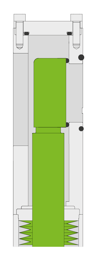
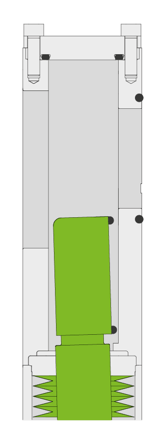
Read moreThe 04.2 Transfer Valve with L-VAT technology is especially suited for corrosive processes such as etch or CVD. The L-VAT technology provides a J-motion of the gate by a single-shaft pneumatic actuator. In a J-motion, the gate is moved vertically into close position – without any contact to the valve body – and in the final movement it is pushed horizontally to the gate seat, with the seal touching the gate seat with a fixed force, related to the connected air pressure.
To minimize particle generation and activation, the gates are fitted with vulcanized seals. This is a highly reliable and more durable sealing solution then a standard O-ring sealing, although standard O-ring sealing is available as an option. The shaft feedthrough is sealed with highly durable metal welded bellows.
In case of power failure, the 04.2 can be pneumatically locked in close and open position by an optional check valve.
The 04.2 Transfer Valve with L-VAT is designed for extended maintenance free operation (≤ 3 million cycles until first service).
Already installed in hundreds of demanding applications in various semiconductor production processes, the 04.2 series has proven its outstanding reliability. With a robust design as well as reduced and easy maintenance, the 04.2 series convinces in all aspects.


The 04.2 Transfer Valve with L-VAT is always tailored to customer specifications. Nevertheless, four basic design types are predefined: two valve types with different rear side openings and two insert types with inside or outside chamber valve seat.
The valve body material options are aluminum, hard anodized or nickel-plated. Gate and bonnet seals are in FKM or FFKM. Other sealing materials are available on request.
Features:
Benefits:
| Sizes | 46 x 236 mm to 50 x 336 mm (1.81" x 9.29" to 1.97" to 13.23") | ||
|---|---|---|---|
| Actuator | Pneumatic | Double acting with position indicator | |
| Body Material | Aluminum | ||
| Feedthrough | Bellows | ||
| Leak Rate | Valve Body | < 1 × 10⁻⁹ mbar ls-1 | |
| Valve Seat | < 1 × 10⁻⁹ mbar ls-1 | ||
| Pressure Range | 1 × 10⁻⁹ mbar to 1.2 bar (abs) | ||
| Differential Pressure | On the Gate | ≤ 1.2 bar | |
| At Opening | ≤ 30 mbar | ||
| Cycles until first Service | ≥ 3 Million | ||
| Temperature | Valve Body | ≤ 50 °C - ≤ 120 °C | |
| Gate | ≤ 50 °C - ≤ 120 °C | ||
| Heating and Cooling Rate | ≤ 40 °C h-1 | ||
| Temperature Difference Seat/Gate | < 40 °C | ||
| Material | Valve Body,Gate, Service Cover | EN AW-6082 (3.2315), EN AW-6061 (3.3211) | |
| Shaft, Bellows end pieces | AISI 316L (1.4435) | ||
| Bellows | AISI 633 (AM 350) | ||
| Seal | Bonnet | FKM (Viton®) | |
| Gate | FKM (Viton®) | ||
| Mounting Position | Actuator down | ||
| Impulse Solenoid valve | 24 VDC, 2.5 W (others on request) | ||
| Position Indicator: Contact Rating | Voltage | ≤ 50 VDC | |
| Current | ≤ 250 mA | ||
| Power | ≤ 10 W | ||
| Connection | 9 pin subminiature D | ||
| Compressed Air Connection | Without Solenoid Valve | Internal Threads ⅛“ ISO/NPT | |
| With Solenoid Valve | Internal Threads M5 | ||